EMBEDDED C
If you are reading this article , believe me in the next few hours , I will make you able to write your own C PROGRAM for the basic applications in embedded system and robotics.
How to Read :
1.Read each line slowly(feel it) and imagine what it really means .If you are not in mood or you have any other things/work to think , it is recommended that Don't read this article .
2.For better understanding run the written programs in KEIL SIMULATOR
NOTE-This article is only for beginners
why C ?
A good understanding of "C" data type can help programmers to create smaller size hex file in applications where we have "memory size" constraints.
Unsigned char
* 8 bit data type
* Range : 0-255 ( 00-FF )
note- By default (if you do not mention its type ) the char data type variable is assumed to be Signed char type.
signed char
* 8 bit data type
* Range :(-128) to (+127)
Use-Temperature representation , Digital calculator etc
Unsigned int
This is most common data type which is used in almost all the applications
* 16 bit data type
* Range : 0-65535 ( 0000-FFFF )
note- 1 . By default (if you do not mention its type ) the int data type variable is assumed to be Signed type.
2 . do not use Unsigned int in places where unsigned char will do the job.
sbit
sbit stands for Single bit . All data types above are BYTE ADDRESSABLE but in embedded applications we need to play in bits also.
variable of this type can be assigned to any particular bit of a REGISTER which are BIT ADDRESSABLE.
* 1 bit data type
e.g P0 , P1 ,P2 , P3 are bit addressable registers having 8 bit in each .
you can assign 3rd bit of P2 to any variable of type sbit
Bit and sfr
TIME DELAY
Two Ways :
using for loop
using TIMER
but here in this section i will discuss only the for loop method.
why we need time delay ?
how to give time delay ?
In almost all application we need some form of delay , for e.g in traffic light control we have to give delay between each colour glow.suppose we want to monitor temperature of blast furnace , we don't want data in milliseconds interval rather we want it in some 2second , 3second delay.University bell can be the best example of precise delay.
There are two ways to give delay :
Using for loop and using 8051 timer .
8051 timer(Precise time control) , i will explain later.Right now i will explain how to give delay using for loop .
e.g for(i=0;i<500;i++)
{
}
This for loop will be executed 500 number of Times .Since there is nothing inside the loop ,the loop is not doing any operation here rather it is giving delay here.Consider time taken to execute each Iteration is 6 ns
TIME DELAY = no of iterations * time taken to execute each iteration
=500*6 =3000 ns
so accordingly by changing the value of no of iterations we can manipulate the delay.
now see the time gap of each led glow :(change is only the no of iterations in loop)
I/O operations:
Two types :
1. Byte size i/o operations
2. Bit size i/o operations
there are 4 ports in 8051 as i have explained earlier (PO,P1,P2,P3) :
P0.0 P1.0 P2.0 P3.0
P0.1 P1.1 P2.1 P3.1
P0.2 P1.2 P2.2 P3.2
P0.3 P1.3 P2.3 P3.3
P0.4 P1.4 P2.4 P3.4
P0.5 P1.5 P2.5 P3.5
P0.6 P1.6 P2.6 P3.6
P0.7 P1.7 P2.7 P3.7
Each port has 8 pin.So we can access the port in two ways ,either we can access the whole port or we can access any particular bit of port.
SOME TERMS :
P2=0x _ _ ; // This is term used to assign any value to any port. I have left Two blanks after 0x,which is used to provide any value to the mentioned port. See the diagram :
(0x stands for hexadecimal value)

In the above diagram we can see how we can assign any value(0 to 255) to any port using hexadecimal notation. In the above diagram P2=0xB5 ; P3=0x46 ; P1=0xB1 ; P0=0x06 and so on.
There are two interpretations of the line :
P2=0xB5 ;
1.When it is just used after the main function and before loop, then it is called
"calibration of port" i.e make that port as an input port.Suppose you want to take an input from any port then first you need to calibre that port as above.
Now the next question is how many pins i have to calibrate? . This leads to another extremely important concept .
P2=OxB5 .Now see the first row of the above diagram .
(1 , 3 , 6 )th bit of P2 is zero .i.e if you are using this statement in your program it will reject the i/p's coming through bits 1 ,3 ,6 .In other word you are only concerned with the bits other than 1 ,3 ,6.
2. To give o/p
MEANING OF 1 . unsigned int a=P3;
2. unsigned int a=P3&0x50;
now believe me , just understand ( feel) the above 2 statements and you can write C code for 1000 applications.
The first one tells , declare one variable "a" of type unsigned int and assign it to point P3 ,in other word "a" is alias for P3.
The second one is the most common , and used to mask or filter certain bits of P3. Suppose I want to use only 4rth and 6th bit of P3 ,Then We perform "&" (AND operation ) with the i/p coming from the port P3 like above .So "a" variable only knows about 4rth and 6th bit of P3.
and except this two bits all bits of this variable is assign to zero.
Now ready for your first c program :(P89V51RD2 -Philips)
Qn: I have connected output of two motion sensor "M1" and "M2" to P3.4 and P3.6 , i have put M1 to room "R1" and M2 to room "R2" . I have also connected two alarm "A1" and "A2" to P2 such that :
P2.0 P2.1 ALARM ACTIVATED ||| P2.2 P2.3 ALARM ACTIVATE
if 1 0 "A1" ||| 1 0 "A2"
if 0 0 "A1" deactivated ||| 0 0 alarm "A2' deactivated

Now suppose two thief enters the house to steal , they enters the room R1 and R2 randomly.
Now you have to activate the alarm A1 if someone tries to enter R1 and activate alarm A2 if someone tries to enter R2 ,or activate both alarms if they enters at the same point of time (assume that sensor give 1 if it detect any motion in room)
sol : Just give some time to think and analyse this real time problem .now using the concepts
which i have discussed and some very basic concept of C you can understand the below mentioned program by Ur self :
note : this program is already tasted in real time , so any comments regarding the error in this program is absurd :
#include<reg51.h>
#include<stdio.h>
void delay(unsigned int);
int main()
{ // Port P3
unsigned int b=P3&0x50; // Masking of Port P3 to read values of only P3.4 and P3.6, 7 6 5 4 3 2 1 0
while(1) // 0 1 0 1 0 0 0 0 = 0x50
{ // Infinite loop to continue the process forever...
b=P3&0x50; // Read the input value of Pins P3.6 and P3.4 and store in variable b
switch(b) // Take action according to the status of Pins P3.4 and P3.6
{
case 0x40: P2=0x01; // If M1 is active, Start Alarm A1
delay(350); // Delay for Alarm
P2=0x00; // Stop the alarm A1
break;
case 0x10: P2=0x04; // If M2 is active, Start Alarm A2
delay(350); // Delay for Alarm
P2=0x00; // Stop the alarm A2
break;
case 0x00: P2=0x05; // If M1 and M2 is active, Start Alarm A1 and A2
delay(350); // Delay for Alarm
P2=0x00; // Stop the alarm A1 and A2
break;
default: continue; // In case of any Invalid Input, Repeat the process.
}
}
}
void delay(unsigned int time) // Function for Time Delay
{
unsigned int i,j;
for (i=0;i<time;i++)
for (j=0;j<1275;j++);
}
Just by reading the comments you can understand the program by Ur self .
Now i will explain BIT WISE i/o operations .
BIT-WISE INPUT OUTPUT OPERATIONS:
Use of "sbit" data type in bit wise input output operations .For the problem above, you can also use two single bit variable to monitor P3.4 and P3.6 and activate the alarm accordingly :
#include<reg51.h>
#include<stdio.h>
sbit m_sensor_1=P3^4; //declare variable of type single bit and assign it to monitor P3.4
sbit m_sensor_2=P3^6; //..........
void delay(unsigned int);
void main(void)
{
m_sensor_1=1; //set P3.4 as an i/p pin
m_sensor_2=1; //set P3.6 as an i/p pin
while(1)
{
if( (m_sensor_1==0) && (m_sensor_2==1) )
{
P2=0x01;
delay(350);
P2=0x00;
}
else if( (m_sensor_1==1) && (m_sensor_2==0) )
{
P2=0x04;
delay(350);
P2=0x00;
}
else if( (m_sensor_1==0) && (m_sensor_2==0) )
{
P2=0x05;
delay(350);
P2=0x00;
}
else
continue;
}
}
void delay(unsigned int time) // Function for Time Delay
{
unsigned int i,j;
for (i=0;i<time;i++)
for (j=0;j<1275;j++);
}
**NOTE: This program is tasted in real time(P89V51RD2) , so there is no error in this program .
This program is easy to understand ,So make some changes and simulate in KEIL S/W to see what is the o/p you are getting.
So this was discussion about i/o operation .
Logical operations :
In this Section i only explain what is the need of these operators (application point of view) .
This is called most important and powerful feature of "C" language ,because of its ability to perform "bit manipulation" and many books in "C" does not cover this important topic.
e.g AND(&&) , OR( || ) , NOT ( ! ) , BIT WISE AND(&) , OR( | ) , EX-OR ( ^ ) , INVERTER(~) , and the most interesting ones are : Shift Right (>>) and Shift Left(<<) .
These bit wise operators are widely used in software engineering for embedded system and control.
If you are reading this article , believe me in the next few hours , I will make you able to write your own C PROGRAM for the basic applications in embedded system and robotics.
How to Read :
1.Read each line slowly(feel it) and imagine what it really means .If you are not in mood or you have any other things/work to think , it is recommended that Don't read this article .
2.For better understanding run the written programs in KEIL SIMULATOR
NOTE-This article is only for beginners
TOPICS COVERED :
1. Why C ?
2. Data Types
3. Time delay
4. I/O operations
5. Logical & Arithmetic operations
6. Data Serialization
why C ?
- Assembly language is "tedious" & "time consuming" while C is easier to write and less time consuming.
- MODULAR property : Easy to modify and Update . This property of C allows the programmer to divide the main task in to sub-tasks where each sub task is independent of each other so that it can be distributed among 5 or 6 programmers .The Last stage of this is to assemble all the sub tasks to perform the main task. The sub tasks are called functions .Now suppose any function has got some error or defect or simply you want to optimize/enhance/modify it ,then there is no need to change the whole program ,Simply you can give this particular function to the person it belong to rectify it.
- You can import/reuse "some already built functions" from library in order to reduce cost & time.
A good understanding of "C" data type can help programmers to create smaller size hex file in applications where we have "memory size" constraints.
Unsigned char
* 8 bit data type
* Range : 0-255 ( 00-FF )
note- By default (if you do not mention its type ) the char data type variable is assumed to be Signed char type.
signed char
* 8 bit data type
* Range :(-128) to (+127)
Use-Temperature representation , Digital calculator etc
Unsigned int
This is most common data type which is used in almost all the applications
* 16 bit data type
* Range : 0-65535 ( 0000-FFFF )
note- 1 . By default (if you do not mention its type ) the int data type variable is assumed to be Signed type.
2 . do not use Unsigned int in places where unsigned char will do the job.
sbit
sbit stands for Single bit . All data types above are BYTE ADDRESSABLE but in embedded applications we need to play in bits also.
variable of this type can be assigned to any particular bit of a REGISTER which are BIT ADDRESSABLE.
* 1 bit data type
e.g P0 , P1 ,P2 , P3 are bit addressable registers having 8 bit in each .
you can assign 3rd bit of P2 to any variable of type sbit
Bit and sfr
- In ROM there is bit addressable memory from 20H-2FH (total 16 byte = 16*8 bit ) which you can use it for data storage in your applications
- sfr is 8bit data type ,stands for special function registers which is BYTE ADDRESSABLE used to assign registers having address 80H to FFH .
TIME DELAY
Two Ways :
using for loop
using TIMER
but here in this section i will discuss only the for loop method.
why we need time delay ?
how to give time delay ?
In almost all application we need some form of delay , for e.g in traffic light control we have to give delay between each colour glow.suppose we want to monitor temperature of blast furnace , we don't want data in milliseconds interval rather we want it in some 2second , 3second delay.University bell can be the best example of precise delay.
There are two ways to give delay :
Using for loop and using 8051 timer .
8051 timer(Precise time control) , i will explain later.Right now i will explain how to give delay using for loop .
e.g for(i=0;i<500;i++)
{
}
This for loop will be executed 500 number of Times .Since there is nothing inside the loop ,the loop is not doing any operation here rather it is giving delay here.Consider time taken to execute each Iteration is 6 ns
TIME DELAY = no of iterations * time taken to execute each iteration
=500*6 =3000 ns
so accordingly by changing the value of no of iterations we can manipulate the delay.
now see the time gap of each led glow :(change is only the no of iterations in loop)
I/O operations:
Two types :
1. Byte size i/o operations
2. Bit size i/o operations
there are 4 ports in 8051 as i have explained earlier (PO,P1,P2,P3) :
P0.0 P1.0 P2.0 P3.0
P0.1 P1.1 P2.1 P3.1
P0.2 P1.2 P2.2 P3.2
P0.3 P1.3 P2.3 P3.3
P0.4 P1.4 P2.4 P3.4
P0.5 P1.5 P2.5 P3.5
P0.6 P1.6 P2.6 P3.6
P0.7 P1.7 P2.7 P3.7
Each port has 8 pin.So we can access the port in two ways ,either we can access the whole port or we can access any particular bit of port.
SOME TERMS :
P2=0x _ _ ; // This is term used to assign any value to any port. I have left Two blanks after 0x,which is used to provide any value to the mentioned port. See the diagram :
(0x stands for hexadecimal value)

In the above diagram we can see how we can assign any value(0 to 255) to any port using hexadecimal notation. In the above diagram P2=0xB5 ; P3=0x46 ; P1=0xB1 ; P0=0x06 and so on.
There are two interpretations of the line :
P2=0xB5 ;
1.When it is just used after the main function and before loop, then it is called
"calibration of port" i.e make that port as an input port.Suppose you want to take an input from any port then first you need to calibre that port as above.
Now the next question is how many pins i have to calibrate? . This leads to another extremely important concept .
P2=OxB5 .Now see the first row of the above diagram .
(1 , 3 , 6 )th bit of P2 is zero .i.e if you are using this statement in your program it will reject the i/p's coming through bits 1 ,3 ,6 .In other word you are only concerned with the bits other than 1 ,3 ,6.
2. To give o/p
MEANING OF 1 . unsigned int a=P3;
2. unsigned int a=P3&0x50;
now believe me , just understand ( feel) the above 2 statements and you can write C code for 1000 applications.
The first one tells , declare one variable "a" of type unsigned int and assign it to point P3 ,in other word "a" is alias for P3.
The second one is the most common , and used to mask or filter certain bits of P3. Suppose I want to use only 4rth and 6th bit of P3 ,Then We perform "&" (AND operation ) with the i/p coming from the port P3 like above .So "a" variable only knows about 4rth and 6th bit of P3.
and except this two bits all bits of this variable is assign to zero.
Now ready for your first c program :(P89V51RD2 -Philips)
Qn: I have connected output of two motion sensor "M1" and "M2" to P3.4 and P3.6 , i have put M1 to room "R1" and M2 to room "R2" . I have also connected two alarm "A1" and "A2" to P2 such that :
P2.0 P2.1 ALARM ACTIVATED ||| P2.2 P2.3 ALARM ACTIVATE
if 1 0 "A1" ||| 1 0 "A2"
if 0 0 "A1" deactivated ||| 0 0 alarm "A2' deactivated

Now suppose two thief enters the house to steal , they enters the room R1 and R2 randomly.
Now you have to activate the alarm A1 if someone tries to enter R1 and activate alarm A2 if someone tries to enter R2 ,or activate both alarms if they enters at the same point of time (assume that sensor give 1 if it detect any motion in room)
sol : Just give some time to think and analyse this real time problem .now using the concepts
which i have discussed and some very basic concept of C you can understand the below mentioned program by Ur self :
note : this program is already tasted in real time , so any comments regarding the error in this program is absurd :
#include<reg51.h>
#include<stdio.h>
void delay(unsigned int);
int main()
{ // Port P3
unsigned int b=P3&0x50; // Masking of Port P3 to read values of only P3.4 and P3.6, 7 6 5 4 3 2 1 0
while(1) // 0 1 0 1 0 0 0 0 = 0x50
{ // Infinite loop to continue the process forever...
b=P3&0x50; // Read the input value of Pins P3.6 and P3.4 and store in variable b
switch(b) // Take action according to the status of Pins P3.4 and P3.6
{
case 0x40: P2=0x01; // If M1 is active, Start Alarm A1
delay(350); // Delay for Alarm
P2=0x00; // Stop the alarm A1
break;
case 0x10: P2=0x04; // If M2 is active, Start Alarm A2
delay(350); // Delay for Alarm
P2=0x00; // Stop the alarm A2
break;
case 0x00: P2=0x05; // If M1 and M2 is active, Start Alarm A1 and A2
delay(350); // Delay for Alarm
P2=0x00; // Stop the alarm A1 and A2
break;
default: continue; // In case of any Invalid Input, Repeat the process.
}
}
}
void delay(unsigned int time) // Function for Time Delay
{
unsigned int i,j;
for (i=0;i<time;i++)
for (j=0;j<1275;j++);
}
Just by reading the comments you can understand the program by Ur self .
Now i will explain BIT WISE i/o operations .
BIT-WISE INPUT OUTPUT OPERATIONS:
Use of "sbit" data type in bit wise input output operations .For the problem above, you can also use two single bit variable to monitor P3.4 and P3.6 and activate the alarm accordingly :
#include<reg51.h>
#include<stdio.h>
sbit m_sensor_1=P3^4; //declare variable of type single bit and assign it to monitor P3.4
sbit m_sensor_2=P3^6; //..........
void delay(unsigned int);
void main(void)
{
m_sensor_1=1; //set P3.4 as an i/p pin
m_sensor_2=1; //set P3.6 as an i/p pin
while(1)
{
if( (m_sensor_1==0) && (m_sensor_2==1) )
{
P2=0x01;
delay(350);
P2=0x00;
}
else if( (m_sensor_1==1) && (m_sensor_2==0) )
{
P2=0x04;
delay(350);
P2=0x00;
}
else if( (m_sensor_1==0) && (m_sensor_2==0) )
{
P2=0x05;
delay(350);
P2=0x00;
}
else
continue;
}
}
void delay(unsigned int time) // Function for Time Delay
{
unsigned int i,j;
for (i=0;i<time;i++)
for (j=0;j<1275;j++);
}
**NOTE: This program is tasted in real time(P89V51RD2) , so there is no error in this program .
This program is easy to understand ,So make some changes and simulate in KEIL S/W to see what is the o/p you are getting.
So this was discussion about i/o operation .
Logical operations :
In this Section i only explain what is the need of these operators (application point of view) .
This is called most important and powerful feature of "C" language ,because of its ability to perform "bit manipulation" and many books in "C" does not cover this important topic.
e.g AND(&&) , OR( || ) , NOT ( ! ) , BIT WISE AND(&) , OR( | ) , EX-OR ( ^ ) , INVERTER(~) , and the most interesting ones are : Shift Right (>>) and Shift Left(<<) .
These bit wise operators are widely used in software engineering for embedded system and control.
1. "&" operator -This operator is used to mask certain bits of any ports or registers , as we have seen how it was used in our first motion sensor program
e.g b=P3&0x50 ; // This will be used for masking operation.
2." |" operator- Suppose we want to set the upper "4" bit of any register or port to "1" ,Then the best way to do this is to perform " |" operation with that port or register.
e.g b=P3 | 0xF0 ; Whatever the value is there "inside the P3" ,after this operation the upper 4 bit of variable "b" will be set to 1.
This is used in "ASCII CONVERSION ".
3." ^ " operator- This is most interesting operator .Have a look what this is capable of :
a.To toggle any bit / byte of a register or ports
Think? [ b=P3^0xFF ]
You can get back P3 by P3=b^0xFF ;
b.Used to see whether two registers or ports has SAME VALUE(compare)
Think? if ( (P3^P2)==0x00 )
printf("P3 and P2 are equal");
c.Used to clear any register/port
Think? if it is XORed with itself e.g b=(P3^P3);
P3=b;
4.Shift Right (>>) and Shift Left(<<) - Now this is more interesting .Now see the diagram :
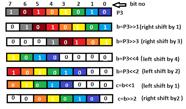 In the above diagram P3=0xAA and if we perform b=P3>>3 we will get b=0x15 ;
This shift operation is used in data serialisation ,which is the next topic.
Data Serialization :
It is the way of sending a byte of data one bit at a time through the single pin of 8051
It is achieved using two method :
1. using SERIAL PORT( RXD,TXD) PIN
2.using shift operator
for better feel of this topic understand the problem completely :
Qn: Write a "C" program to read input(byte) from port P3 of 8051 and send data to pin "P2.4" one bit at a time with some time delay serially , starting from LSB(0th bit) .

RED LED is connected to P2.4 and it glows if P2.4= "1" and OFF if P2.4=" 0" so that for the data given in the diagram it should give output :
Off , on , on , off , on , off , on , on .
Sol: In any type of real time serialization problem just follow the same rule as stated below :
1.Declare variable of sbit data type ,pointing to that pin through which stream of bits has to be sent out
2.Declare variable of sbit data type ,pointing to the 0th( If LSB has to be sent out first) bit
or 7th( If MSB has to be sent out first) bit of ACC(it is bit addressable 8 bit inbuilt register in 8051 )
3.use LEFT SHIFT if MSB has to be sent out first and use RIGHT SHIFT if LSB has to be sent out first .
#include<stdio.h>
sbit LSB_bit=ACC^0; // this single bit variable points to the 0th bit of "ACC" register ( 8 bit )
sbit led_pin=P2^4; // this single bit variable points to the output pin .
void delay(unsigned int); //give some delay after sending each bit
void main(void)
{
unsigned char b;
P3=0xFF; //make P3 as input port
ACC=P3;
delay(50000); //gives approximately 12 second delay here to adjust P3 pins
while(1)
{
for(b=0;b<8;b++) //to give 8 bit through single pin we need 8 iteration
{
led_pin=LSB_bit; //assign 0th bit of "ACC" to output pin
delay(50000); //now again delay
ACC=ACC>>1; //now next higher bit(1st) comes to the 0th place
}
break; //after giving the output terminate the program
}
}
void delay(unsigned int time) // Function for Time Delay
{
unsigned int i,j;
for (i=0;i<time;i++)
for (j=0;j<1275;j++);
}
This program is in readable form , just by reading the comments you can understand it.
This program has been checked in real time application .Comments regarding the error in this program is absurd.
end of this post.....
any suggestion about what you would like to see in the next article or to highlight errors in this articles or for any doubt please drop a line in this column...
or contact : aies.hsprofessionals@gmail.com
upcoming article:
e.g b=P3&0x50 ; // This will be used for masking operation.
2." |" operator- Suppose we want to set the upper "4" bit of any register or port to "1" ,Then the best way to do this is to perform " |" operation with that port or register.
e.g b=P3 | 0xF0 ; Whatever the value is there "inside the P3" ,after this operation the upper 4 bit of variable "b" will be set to 1.
This is used in "ASCII CONVERSION ".
3." ^ " operator- This is most interesting operator .Have a look what this is capable of :
a.To toggle any bit / byte of a register or ports
Think? [ b=P3^0xFF ]
You can get back P3 by P3=b^0xFF ;
b.Used to see whether two registers or ports has SAME VALUE(compare)
Think? if ( (P3^P2)==0x00 )
printf("P3 and P2 are equal");
c.Used to clear any register/port
Think? if it is XORed with itself e.g b=(P3^P3);
P3=b;
4.Shift Right (>>) and Shift Left(<<) - Now this is more interesting .Now see the diagram :

This shift operation is used in data serialisation ,which is the next topic.
Data Serialization :
It is the way of sending a byte of data one bit at a time through the single pin of 8051
It is achieved using two method :
1. using SERIAL PORT( RXD,TXD) PIN
2.using shift operator
for better feel of this topic understand the problem completely :
Qn: Write a "C" program to read input(byte) from port P3 of 8051 and send data to pin "P2.4" one bit at a time with some time delay serially , starting from LSB(0th bit) .

RED LED is connected to P2.4 and it glows if P2.4= "1" and OFF if P2.4=" 0" so that for the data given in the diagram it should give output :
Off , on , on , off , on , off , on , on .
Sol: In any type of real time serialization problem just follow the same rule as stated below :
1.Declare variable of sbit data type ,pointing to that pin through which stream of bits has to be sent out
2.Declare variable of sbit data type ,pointing to the 0th( If LSB has to be sent out first) bit
or 7th( If MSB has to be sent out first) bit of ACC(it is bit addressable 8 bit inbuilt register in 8051 )
3.use LEFT SHIFT if MSB has to be sent out first and use RIGHT SHIFT if LSB has to be sent out first .
#include<reg51.h>
#include<stdio.h>
sbit LSB_bit=ACC^0; // this single bit variable points to the 0th bit of "ACC" register ( 8 bit )
sbit led_pin=P2^4; // this single bit variable points to the output pin .
void delay(unsigned int); //give some delay after sending each bit
void main(void)
{
unsigned char b;
P3=0xFF; //make P3 as input port
ACC=P3;
delay(50000); //gives approximately 12 second delay here to adjust P3 pins
while(1)
{
for(b=0;b<8;b++) //to give 8 bit through single pin we need 8 iteration
{
led_pin=LSB_bit; //assign 0th bit of "ACC" to output pin
delay(50000); //now again delay
ACC=ACC>>1; //now next higher bit(1st) comes to the 0th place
}
break; //after giving the output terminate the program
}
}
void delay(unsigned int time) // Function for Time Delay
{
unsigned int i,j;
for (i=0;i<time;i++)
for (j=0;j<1275;j++);
}
This program is in readable form , just by reading the comments you can understand it.
This program has been checked in real time application .Comments regarding the error in this program is absurd.
end of this post.....
any suggestion about what you would like to see in the next article or to highlight errors in this articles or for any doubt please drop a line in this column...
or contact : aies.hsprofessionals@gmail.com
upcoming article:
- Make your LINE FOLLOWER ROBOT ready in just 2 Hr.
- Wireless control of your ROBOT via PC using TX433 & RX433.
- Wireless communication between two or more ROBOT.
- Physics behind TOUCH PAD DISPLAY.
- Use that TOUCH PAD to remotely control ( wireless control over range 400 ft ,8kbps,434MHZ) your ROBOT .
- Discussion on DIGITAL IMAGE PROCESSING and INTERFACING CAMERA with your kit and your laptop
No comments:
Post a Comment
Note: only a member of this blog may post a comment.